UAV 3.0
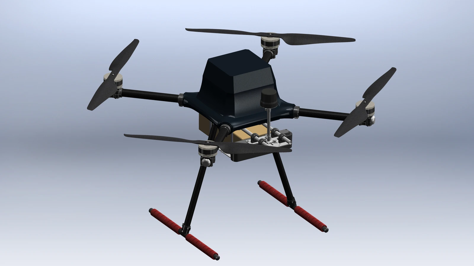
Aerial observation and supply delivery, with protected electronics for flight over water.
Explore UAV 3.0 →Three vehicles, one maritime mission: observe from the air, manoeuvre on the surface and inspect underwater.
We carry RobotX 2024 and SUAS 2025 experience into a weather-protected UAV, a four-thruster USV and our first UUV, developing the systems that connect them.
Official event details ↗Aerial observation and supply delivery, with protected electronics for flight over water.
Explore UAV 3.0 →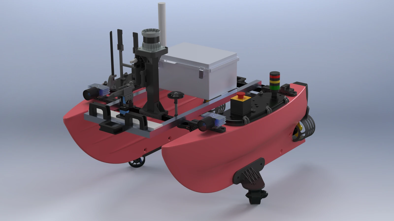
Designed for surface navigation, precision manoeuvring and targeted water delivery.
Explore USV 2.0 →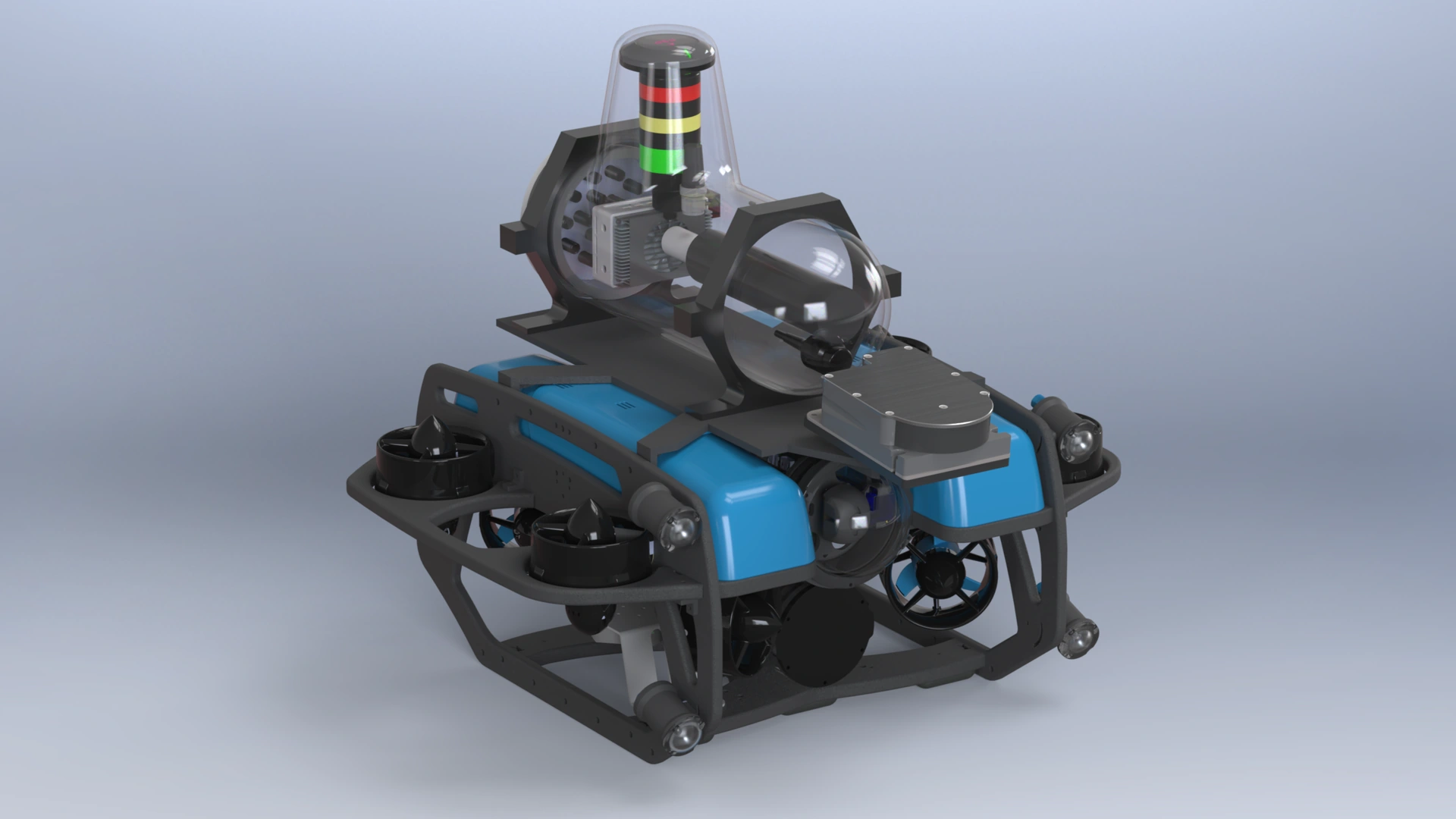
Our first underwater vehicle, combining sonar, visual inspection and local navigation.
Explore UUV 1.0 →Weather protection, precise movement and task-specific mechanisms.
The SUAS camera and computer carry forward, with weather protection and a new delivery mechanism.
Explore UAV 3.0 →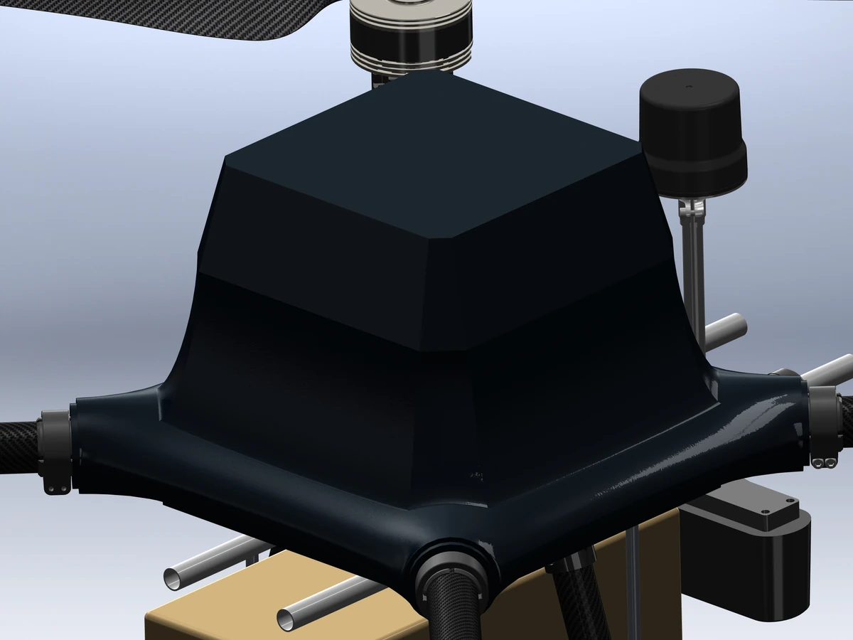
A fully enclosed MJF housing replaces the partial cover, protecting the computer, flight controller and wiring. Waterproof MN4110 motors complete the propulsion changes; sealing and flight checks remain part of integration.
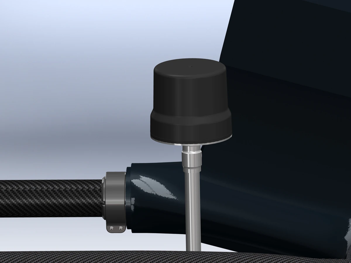
F9P positioning supports mapping light beacons observed from the air. These observations are intended to help the surface vehicle navigate the course.
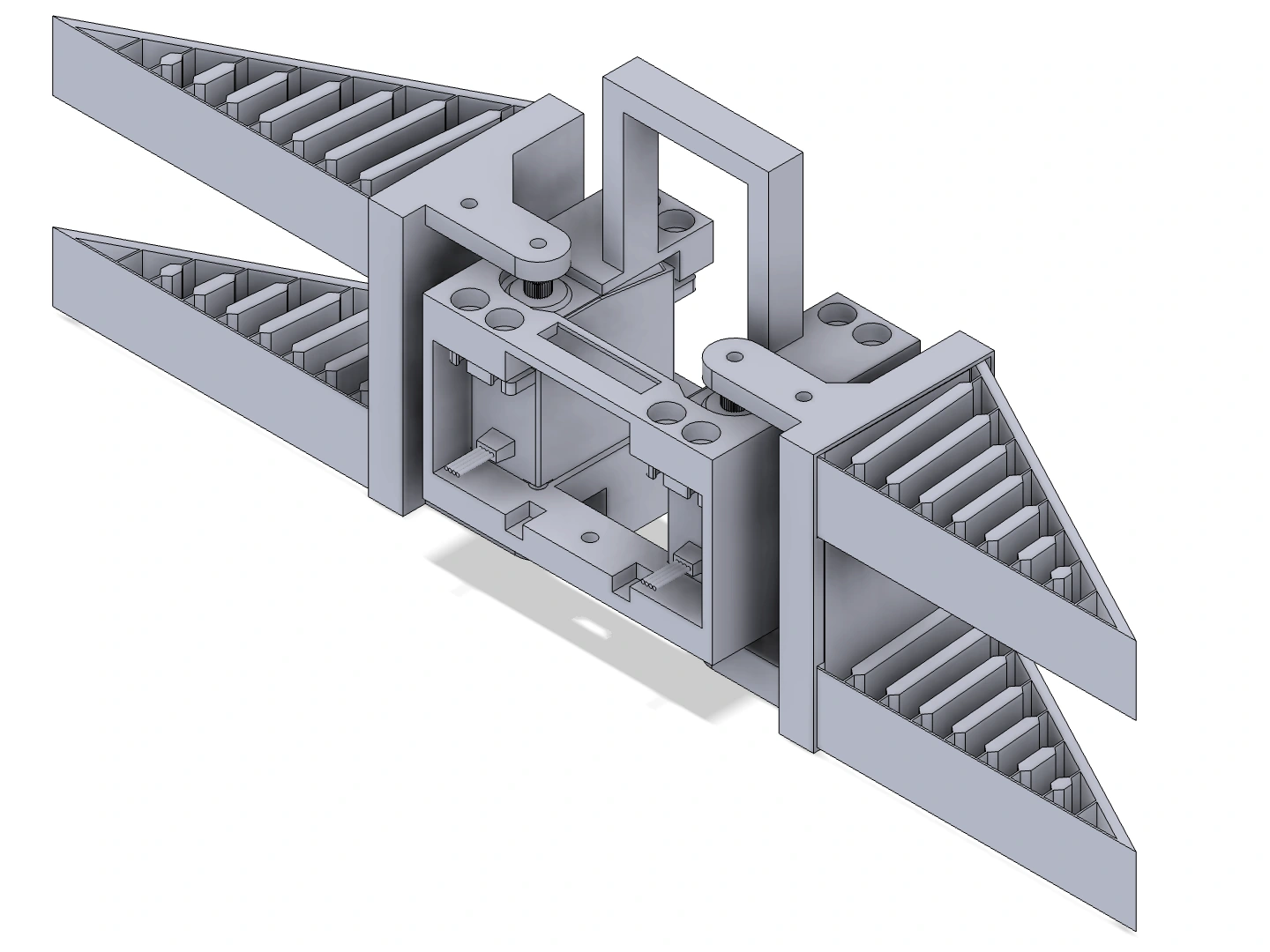
A gripper is in development to transfer supply tins between floating platforms. It builds on our SUAS payload-handling experience, replacing the winch with a pickup-and-release mechanism.
A new surface build designed to approach a dock, hold position and aim a water jet.
Explore USV 2.0 →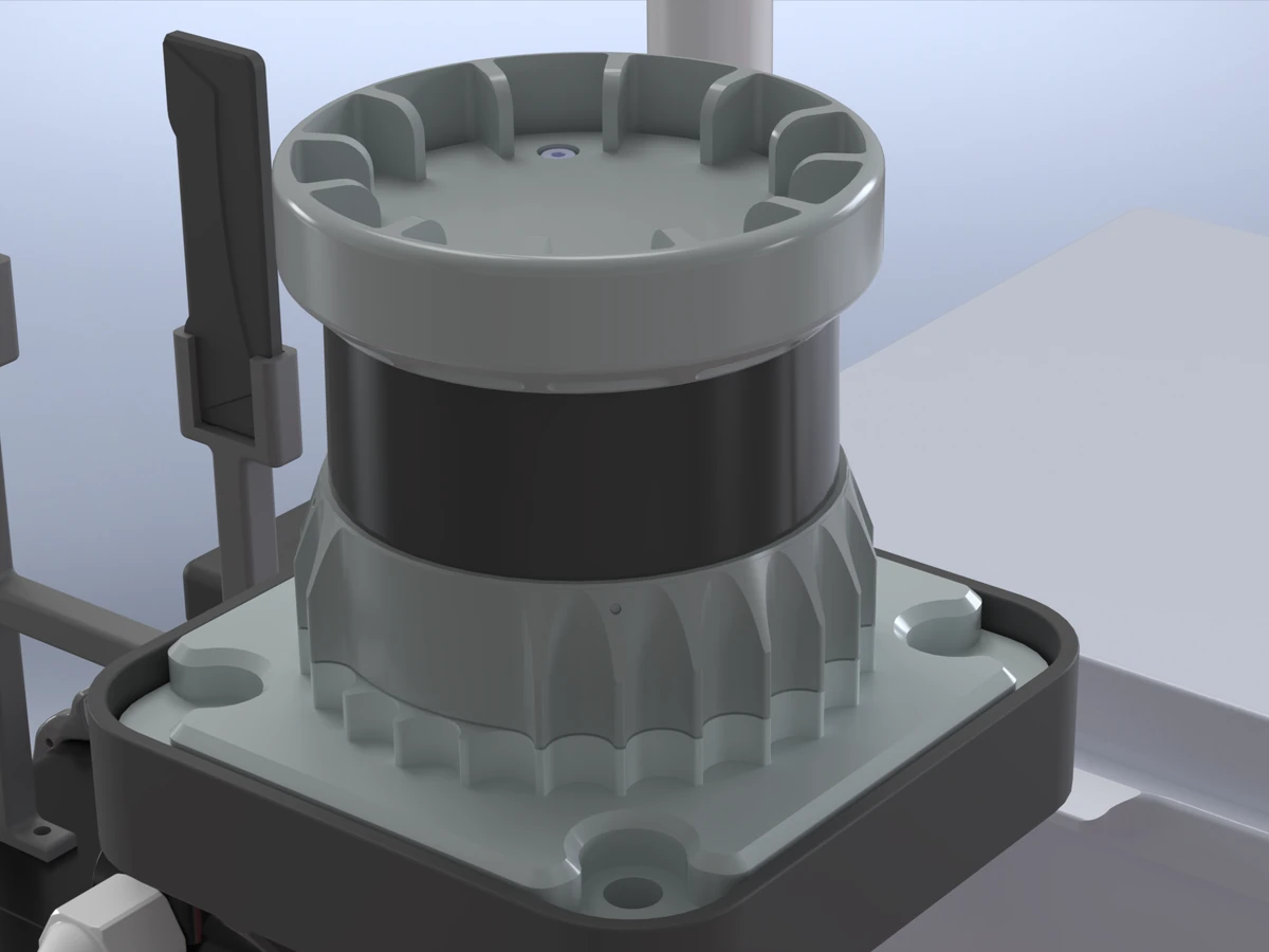
The mast raises an Ouster LiDAR and two Basler cameras above deck equipment. LiDAR measures obstacles; cameras read the lights identifying the permitted bay and active target.
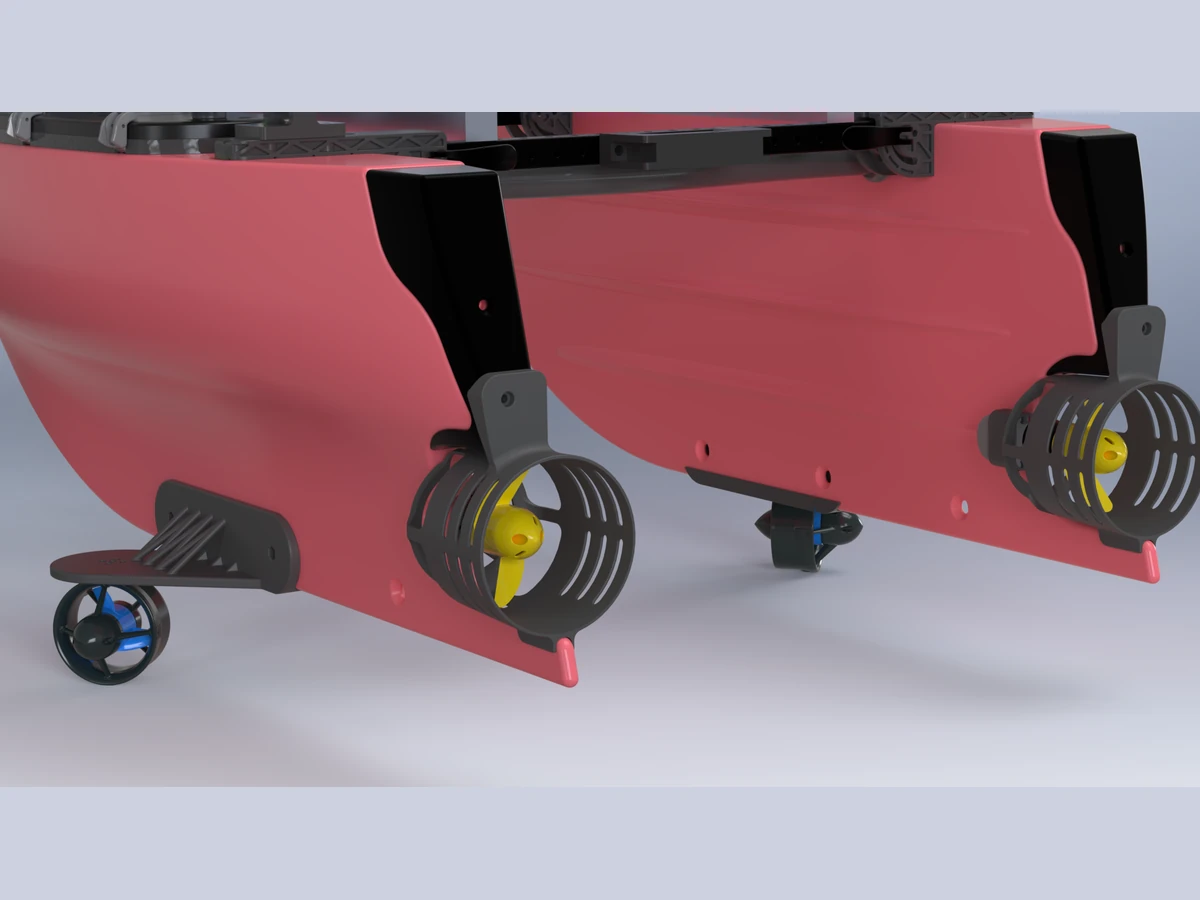
Two diagonal T200s join the stern pair for forward, sideways and turning forces. Custom allocation and physical tuning remain in development to control these motions near the dock.
Thruster-mount analysis →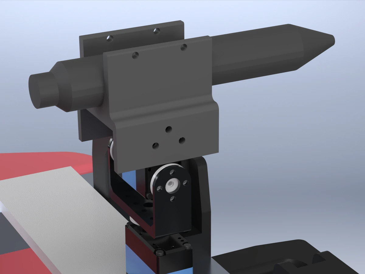
The forward water shooter serves Coordinated Logistics. The design combines visual targeting, nozzle alignment and vessel positioning to reach the active window and check its completion signal.
Our first underwater build brings navigation, inspection and planned repair capability to RobotX.
Explore UUV 1.0 →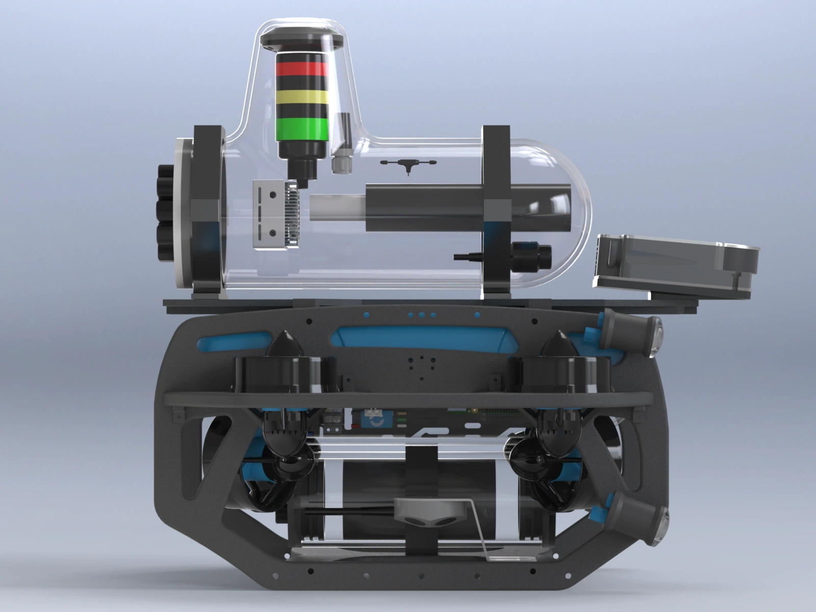
Our upper enclosure houses the companion computer, modem and supporting electronics. Its integration requires checks of buoyancy, trim, heat and cable penetrations.
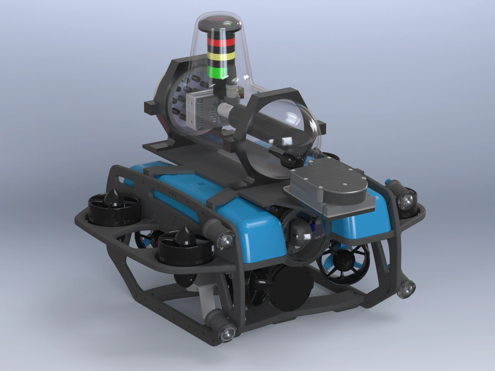
Sonoptix ECHO supplies range and bearing to the pipeline. The camera and lights reveal the colour indicators used to record each segment’s condition.
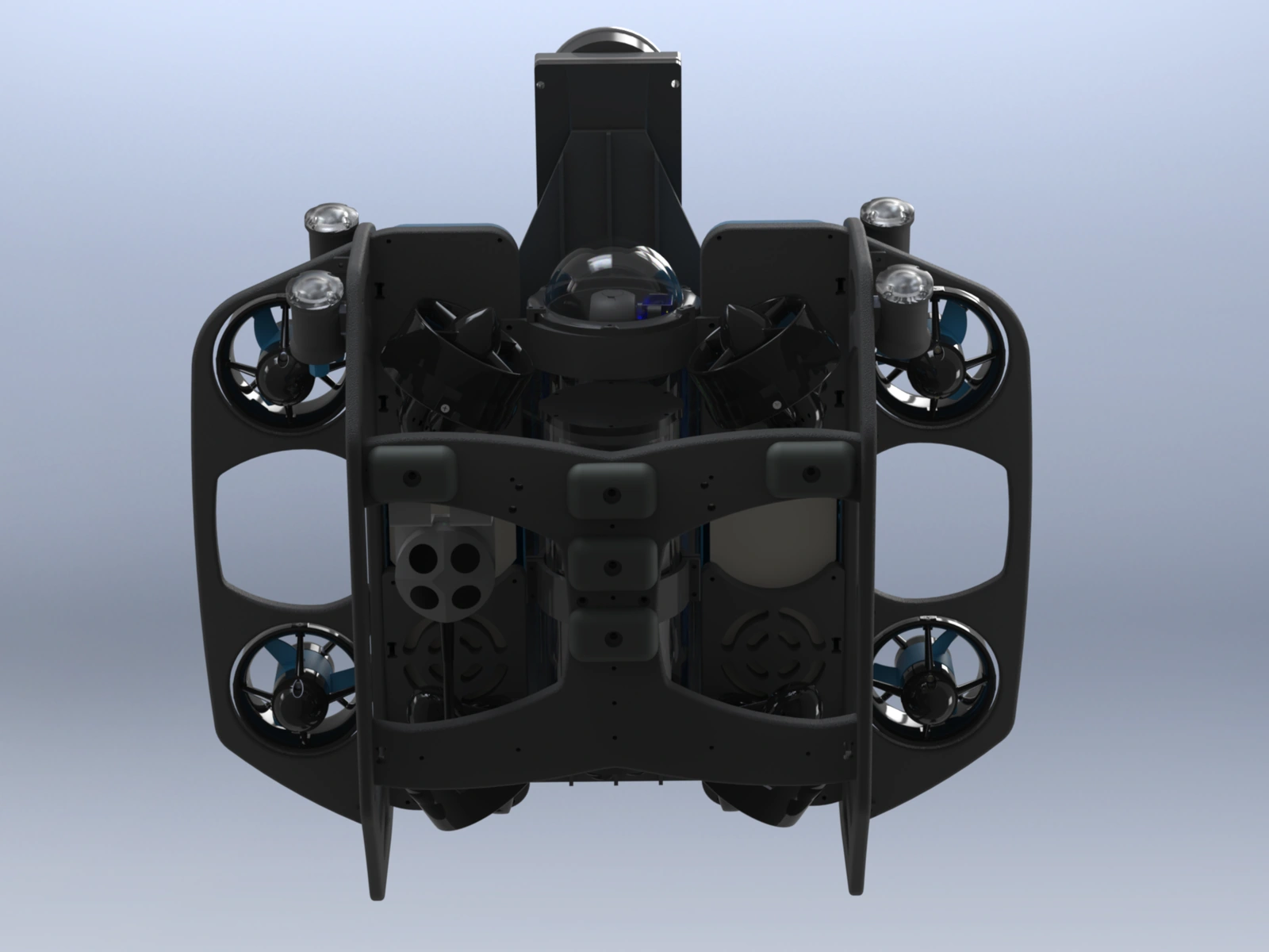
Eight thrusters support movement and attitude control beside the pipeline. A compliant magnetic probe is planned, with stable contact and an indicator change needed to confirm repair.
Power, shutdown, status indication and acoustic sensing.
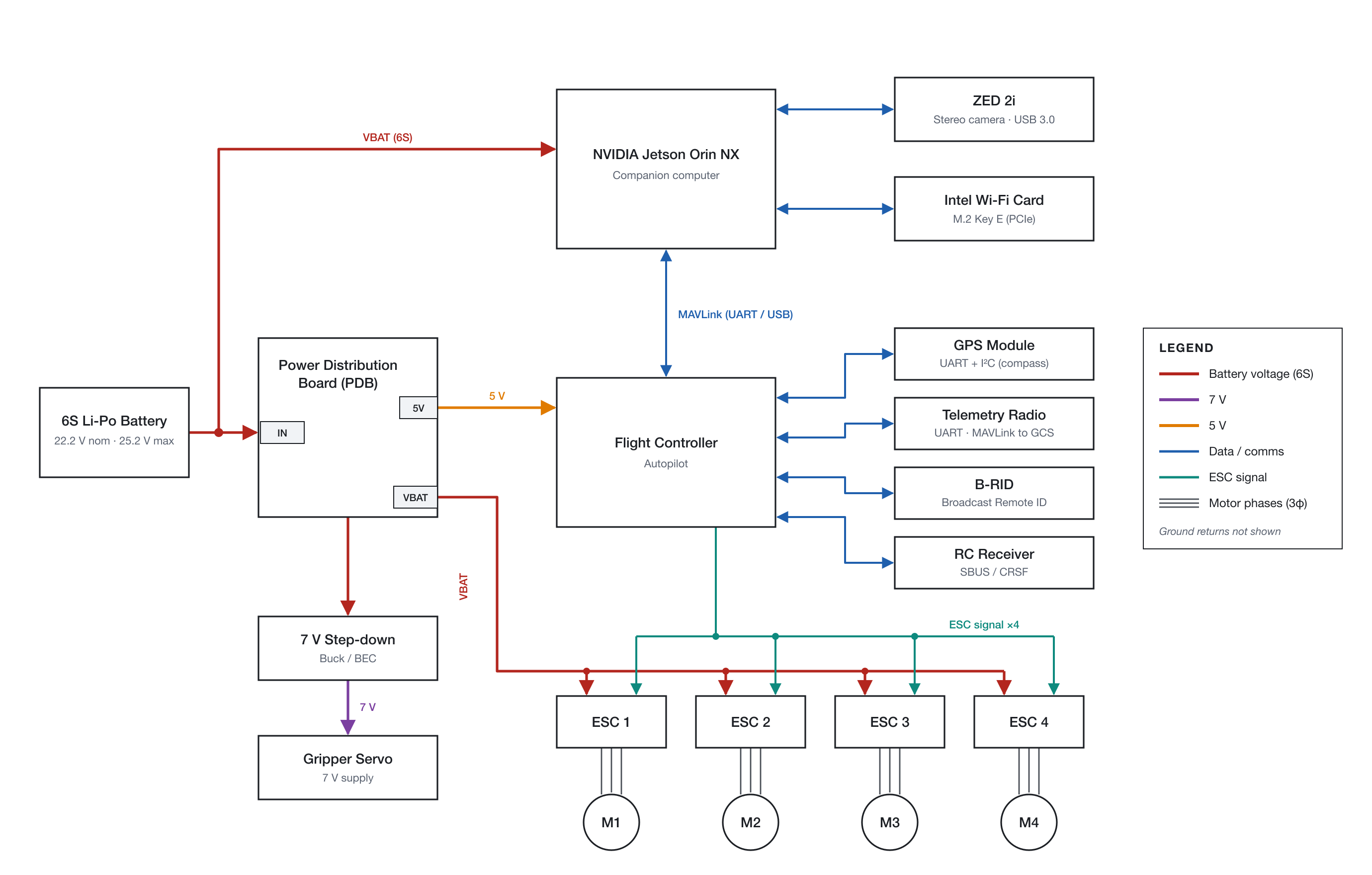
The wiring plan separates propulsion power from regulated supplies for control, computing, sensing and radios. A dedicated step-down branch supplies the gripper servo.
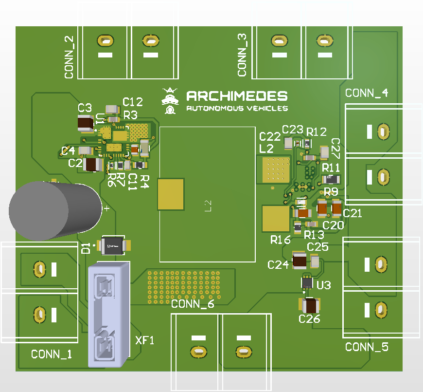
Our USV board provides regulated 12 V, 5 V and 3.3 V supplies, separate from high-current propulsion. Dedicated electronics branches simplify wiring and fault tracing.
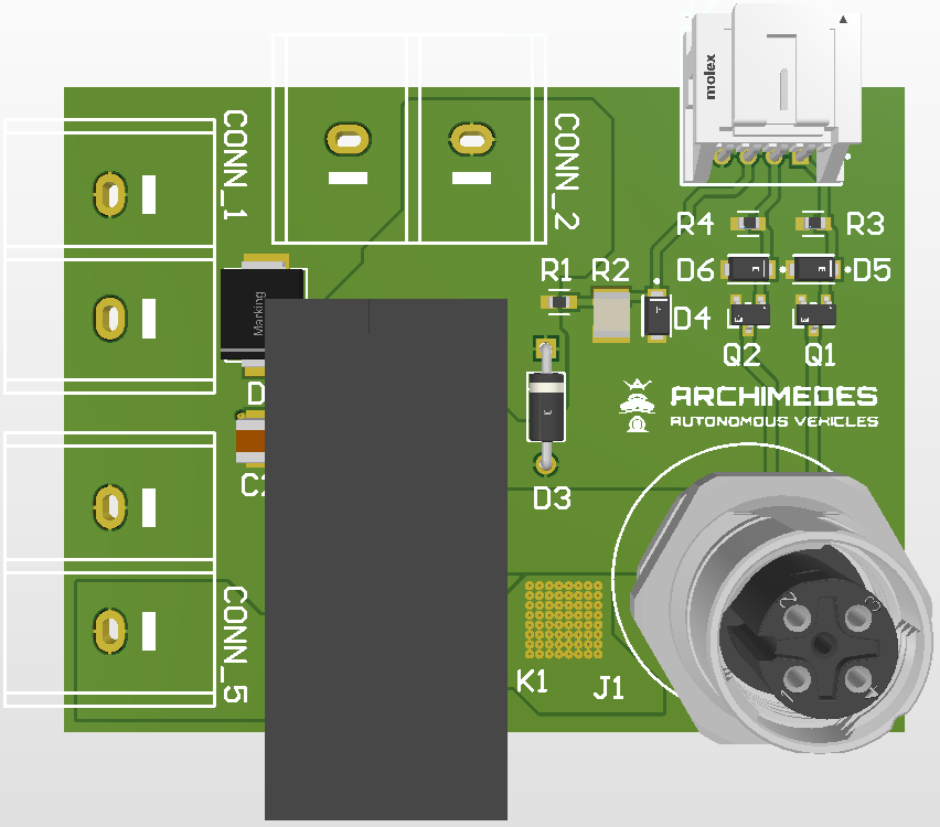
This USV board connects emergency-stop and light-tower hardware. Shutdown inhibits actuation; the tower indicates operating state. The indication and shutdown functions remain distinct.
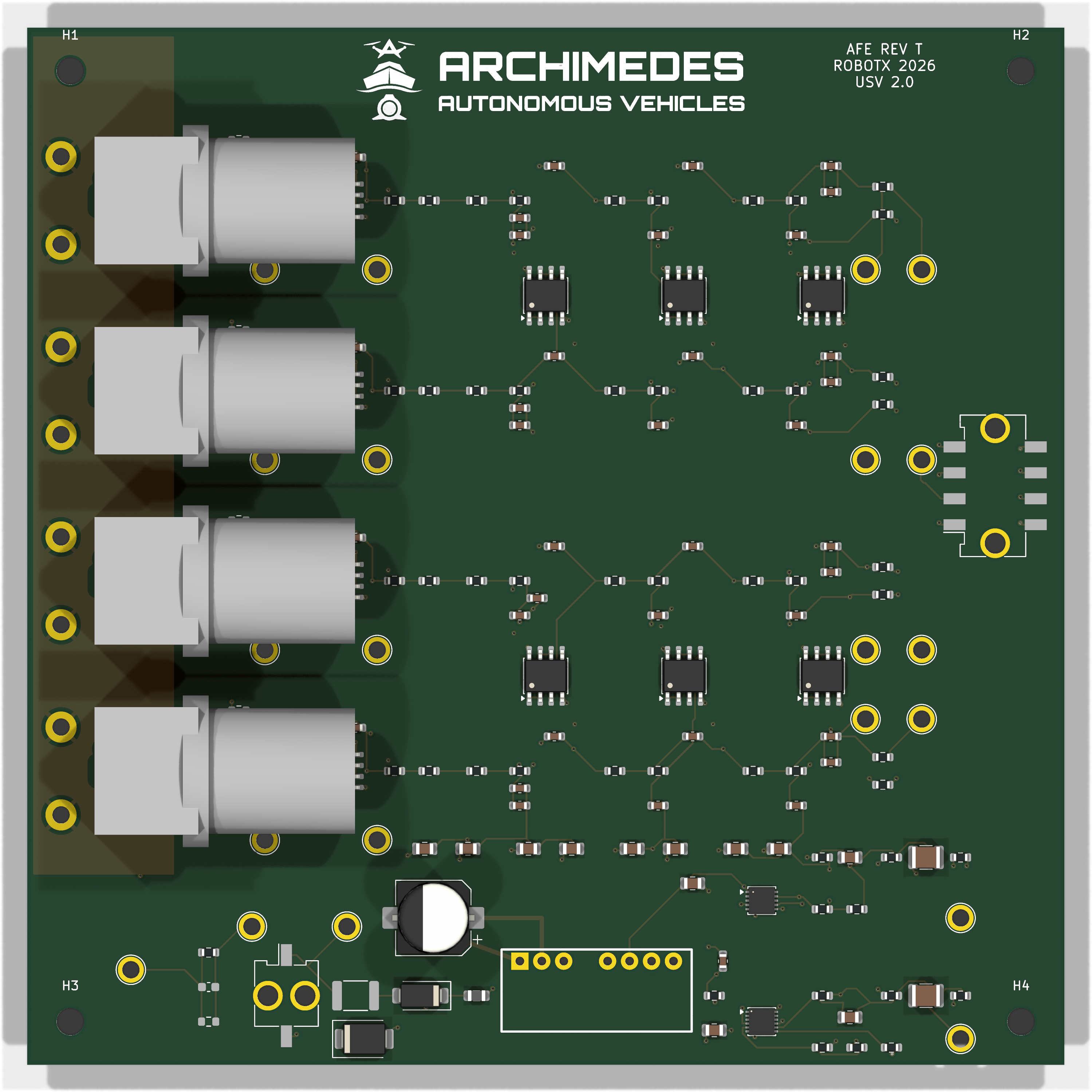
The analogue front end protects, amplifies and filters four hydrophone signals for simultaneous acquisition. Arrival-time differences support pinger localisation, separate from underwater messaging.
Onboard control, shared observations and task requests, with official reporting through Mission OCS.
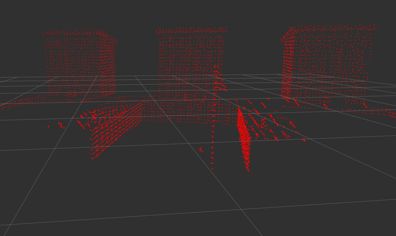
Filtered LiDAR reveals the bay’s geometry in a repeatable scene. Camera observations and vessel control remain to be integrated with obstacle perception.
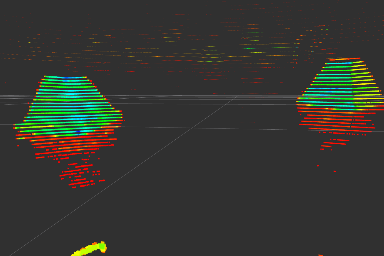
Colour-mapped LiDAR returns reveal real buoy shapes for comparison with simulation. Camera association and tracking remain separate integration steps.
Beacon mapping is in development. Survey and delivery are designed to share one PX4 command interface, with flight reserve and cleared targets governing control handovers.
Route planning handles transit. Near structures, the precision-control design combines forward, sideways and turning forces, with dual-antenna GNSS providing heading while stationary.
Inspection software is in development to combine sonar and camera observations into an ordered pipeline survey, recording each segment’s condition before repair.
From repeatable virtual scenes to physical tests.
Ansys Fluent compares our original and revised thruster mounts, modelling the hull, mount and thruster together to assess drag.
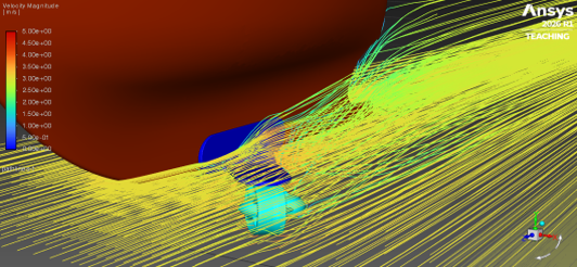
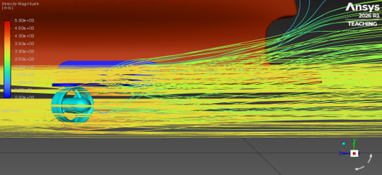
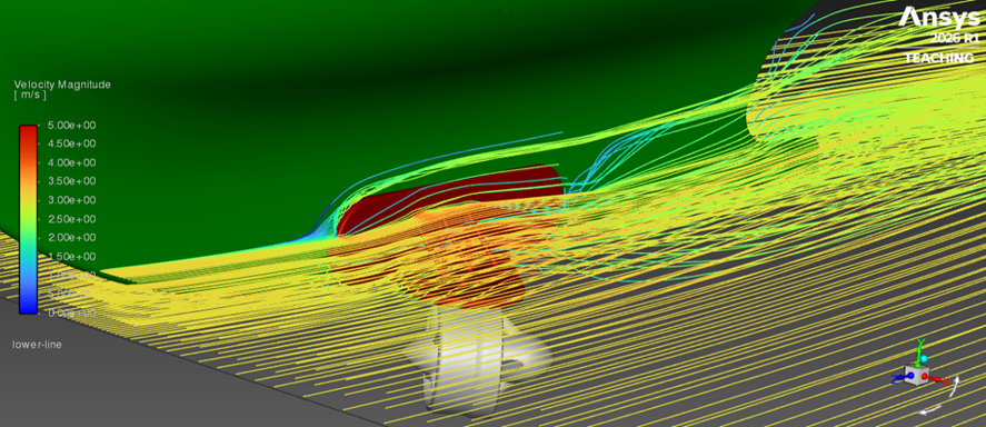
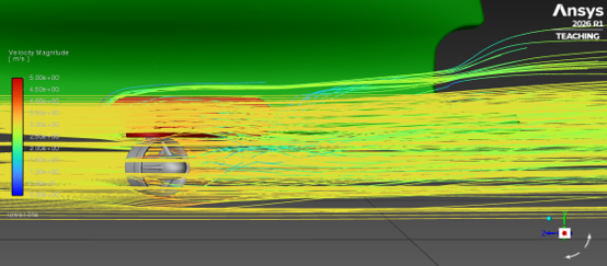
Velocity pathlines, with front views above side views. Select an image to inspect its original detail.
| Component | Original (N) | Revised (N) | Change |
|---|---|---|---|
| Mount | 5.735 | 5.059 | −11.80% |
| Thruster | 25.327 | 24.060 | −5.00% |
| Mount + thruster | 31.062 | 29.118 | −6.26% |
| Hull | 36.391 | 36.954 | +1.55% |
| Modelled assembly | 67.453 | 66.073 | −2.05% |
The revised mount reduces its own drag by 11.8%. Hull drag rises slightly, leaving a 2.05% reduction across the modelled assembly.
Steady RANS, SST k-ω. RX2026 technical design report, pp. 9–14. These are CFD predictions; endurance gains require physical testing.
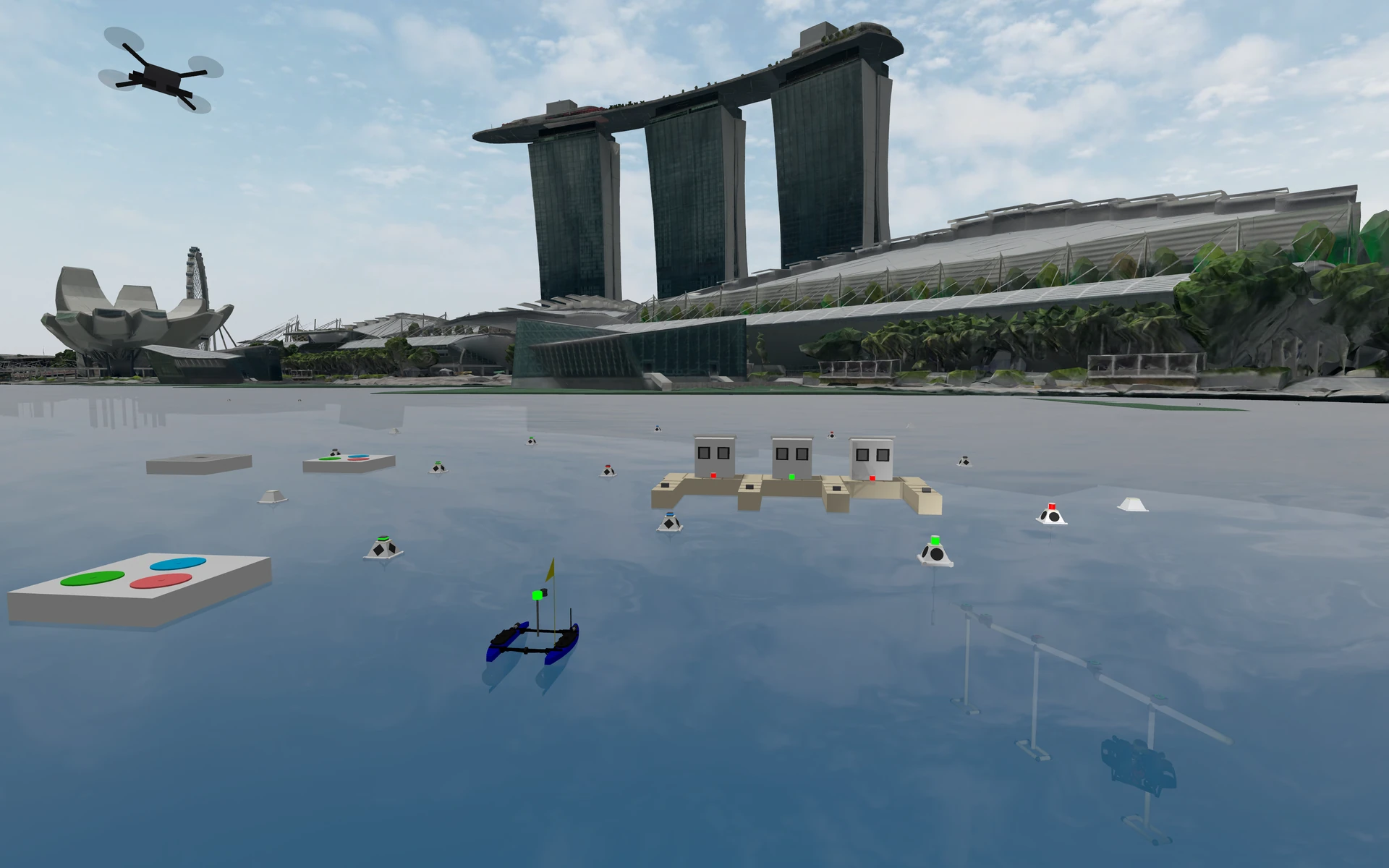
All three vehicle models share a virtual course. Repeatable buoy fields, docking bays and pipelines support perception development and task rehearsals before water testing.
The final 2026 report will be added when it is ready.